Jerome Javelle, SEEQC Inc. — October 7, 2026
The problem with waiting in QEC
Running a quantum computer at scale requires dealing with the imperfections of physical qubits, and it is widely accepted that Quantum Error Correction (QEC) is necessary for this. In practice however, most studied schemes require periods of idling during which the feedback from a global decoder is awaited. During this idling time errors accumulate, and the longer the wait the more complex the resulting syndrome becomes.
Rather than simply speeding up the global decoding loop, SEEQC introduces a complementary approach: acting on errors directly on chip, independently, as frequently as possible during the idling period itself.
SEEQC core technology: millikelvin control electronics
SEEQC designs and manufactures superconducting chips where qubits and Single Flux Quantum (SFQ) qubit control and readout electronics are co-integrated on the same multi-chip module via flip-chip bonding. Our SFQ chip operates at millikelvin temperatures, with clock speeds reaching tens to hundreds of GHz and near-zero static power dissipation — properties that make it uniquely suited to operate in the same cryogenic environment as superconducting qubits.
Qubit readout is performed on-chip based on the Josephson Digital Phase Detector (JDPD), introduced in Di Palma et al., Physical Review Applied 19, 064025 (2023). It digitizes the analogue qubit readout signal directly at the chip level, eliminating the need to transmit analogue signals to room-temperature electronics before digitization.
Control pulses are distributed to qubits using SFQ-based digital demultiplexing, breaking the linear scaling of control lines with qubit count. This full-stack integration of SFQ control electronics was recently demonstrated by SEEQC in Nature Electronics 9, 287–294 (2026), achieving single-qubit fidelities above 99% and up to 99.9% with SFQ control electronics operating alongside the qubits at millikelvin temperature.
The reflex noise filter
The original principle is to detect bit-flip (resp. phase-flip) errors locally on data qubits as early as they occur and act on them straight away. For each data qubit in a stabiliser code, a reflex circuit takes as input the measurement outcomes from all ancillary qubits involved in stabilisers that anti-commute with an X (resp. Z) error on that qubit, and outputs the logical AND of all inputs. If all associated syndromes are set, a corrective pulse sequence is applied immediately (or a Pauli frame update is triggered).
The reflex decoder does not replace the global decoding process — it acts as a first guess using local information and extremely simple logic to simplify the global decoding problem. Unlike pre-decoders, reflex circuits act fully independently with no synchronisation or communication with the global decoder, making them a drop-in addition to any existing QEC stack.
Crucially, as long as the hit rate (correcting a real error) stays above the mirage rate (correcting when no error was present), the reflex circuit cannot degrade the overall error rate. And a faulty reflex circuit is simply transparent — unlike a faulty qubit, it does not invalidate the code, making the approach resilient to fabrication yield variation.
An original framing of error accumulation. Standard QEC analysis treats the full idling period as a single block. The model introduced here — the mille-feuilles model — slices that period into many thin layers, each composed of a syndrome extraction step followed by a direct reflex reaction on chip. A useful analogy: slicing the idling time more finely does not give you a better picture of each error — it gives you better time resolution, like increasing a video frame rate rather than the pixel resolution. You are not seeing more detail per frame, you are catching motion before it compounds.
Within a single reflex layer, Pauli errors accumulate more sparsely than over a full QEC cycle, following (under idealised conditions):
where is the error probability over a full cycle, is the per-layer probability, and is the number of reflex cycles per global QEC round. The error accumulation time becomes independent from global decoder parameters — its accuracy, timing, latency, and bandwidth.
Simulation results
We simulate a memory experiment on a distance-17 rotated surface code using STIM, with T1 = 50 µs, T2 = 30 µs, extra gate error 10⁻⁴, readout error 2%, total idling time 10 µs, and reflex cycle time 250 ns. We use the phenomenological noise model and compare outcomes with and without reflex decoders active.
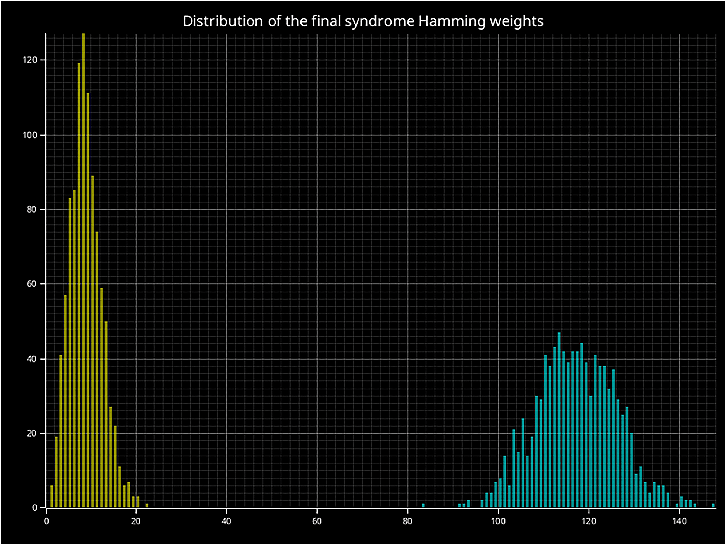
Figure 1: Distribution of syndrome Hamming weights with (yellow) and without (teal) the reflex decoder, from a distance-17 surface code memory experiment (T1 = 50 µs, T2 = 30 µs, additional gate error 10⁻⁴, readout error 2%).
Beyond the syndrome, we also track the accumulated error Hamming weight — the total number of physical qubit errors remaining after reflex corrections. This gives a direct picture of how much work is left for the global decoder.

Figure 2: Distribution of accumulated error Hamming weights with (yellow) and without (teal) the reflex decoder, from a distance-17 surface code memory experiment (T1 = 50 µs, T2 = 30 µs, additional gate error 10⁻⁴, readout error 2%). With the reflex decoder active, error weights are concentrated below 20; without it, they are broadly distributed around 50.
The separation between the two distributions is striking: reflex corrections keep the accumulated error weight low and tightly distributed, whereas without them errors compound into complex Pauli strings that are significantly harder for a global decoder to resolve.
SFQ as the enabler: circuit layout and implementation
As aforementioned in our core technology, the close physical proximity of SFQ logic to the qubits, and its extreme operating speed, are what make it possible to react to errors on timescales far shorter than a conventional QEC cycle — and form the foundation of the reflex decoder concept. For a distance-3 surface code, each data qubit is linked to 2 syndrome qubits related to Z-stabilisers. We use 1 X-reflex circuit per data qubit, firing whenever both connected syndrome qubits are measured to '1'. Border qubits use a next-nearest-neighbour syndrome qubit and only react if this further syndrome is not set.

Figure 3: X-reflex circuits shown with couplings involved in Z-stabilisers. Each diamond-shaped reflex node fires when all connected syndrome inputs are set.

Figure 4: Z-reflex circuits shown with couplings involved in X-stabilisers. The X and Z reflex circuits operate independently and in parallel.
The SFQ reflex circuit reads binary data from syndrome qubits, performs a boolean AND, and triggers a corrective pulse accordingly — all on-die, with no connection to the global decoder. The recent results (Di Palma et al. 2023) that demonstrate on-chip digitisation via JDPDs with SFQ interoperability constitute key evidence to enable the ~250 ns reflex cycle times (200 ns parity check + 50 ns readout). Under these timings, dozens of reflex cycles complete within a single global decoder round, continuously intercepting errors during the idling period rather than waiting for them to accumulate.
Further ongoing work will provide refinement of the reflex circuits to match the experimental noise parameters of real-life QPUs and will improve the number of fals positive and false negatives.